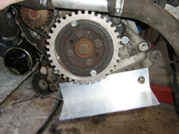
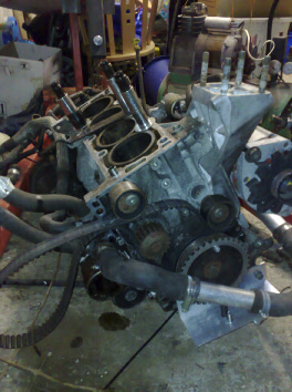
The damper was drilled and tapped to secure the timing wheel while the timing process was carried out. A 3x2 inch piece of aluminium angle was cut down and drilled at the front in about a good place to give some adjustment.
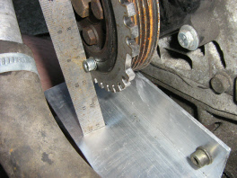
A straight edge was placed across the timing wheel to mark two points on the same line, this line would be where the crank sensor should be mounted.
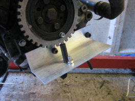
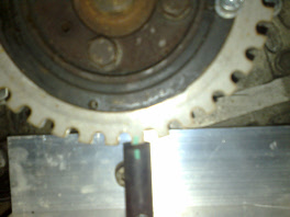
A 14mm hole was drilled in the aluminium angle on the plane previously marked out, the sensor was mounted at about the 6 o’clock point of the engine.
The cylinder head had to come off to check the head gasket, so I decided the DTI the engine for Top Dead Centre and time the trigger wheel to sensor this way. I have done it before with out taking the head off and using a long 3/8 extension on the top of the piston through the spark plug hole.
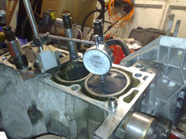
A DTI gauge was mounted on top of the block and centred on the piston, the crank was rotated towards TDC and the needle on the dti gauge watched for it’s highest reading, this was repeated coming back to TDC.
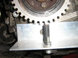
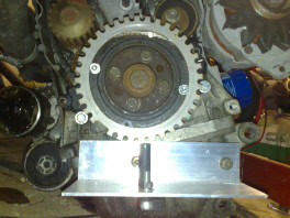
Once the crankshaft TDC was confirmed, the wheel can be seen to be out of alignment
-
The timing wheel was then rotated to be 90 degrees or 9 teeth ahead of the sensor.
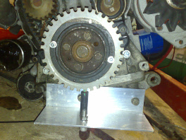
Once the crankshaft timing wheel was timed correctly it was paint marked for the future.
At this point there was still only one mounting point to the engine block as this gave some adjustment in the distance between the sensor and the wheel. Once the distance looked OK the angle was drilled slightly oversize and the bracket securely fixed in place keeping the gap at about 1mm.
The next job is to cut down the massively oversized aluminium and tidy the job up.
Oh yeah -